
How to Plan Control Zones for Linear Architectural Lighting
A practical guide to dividing linear architectural lighting into control zones and DMX512 segments for static, chasing, RGB/RGBW and dynamic facade effects.
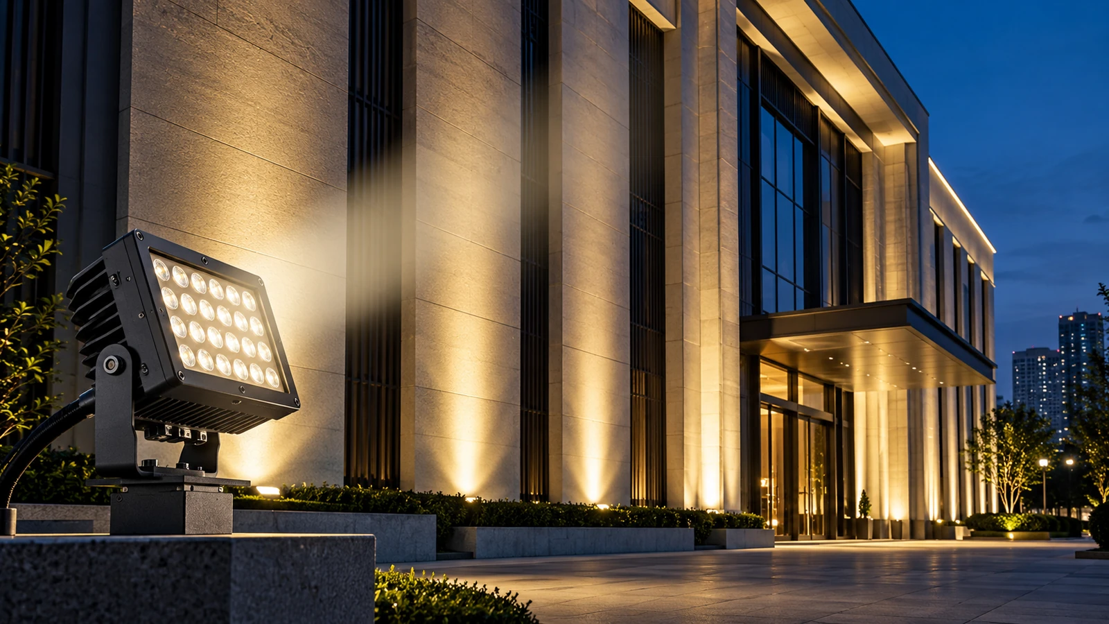
Control zoning determines which luminaires—or which sections inside a luminaire—can respond independently to the lighting system.
For linear architectural lighting, the correct zoning strategy should be defined before installation because it affects fixture configuration, DMX addressing, power distribution, data cabling, programming and maintenance.
The first question is therefore not:
“Which controller should we buy?”
It is:
“What lighting effect does the project actually need?”
1. Start With the Required Effect
Different effects require very different levels of control.
A static single-color outline may need little or no individual pixel control.
An RGB or RGBW facade may require separate architectural zones.
A chasing, meteor, text or video-style effect requires much finer segmentation.
Define the visual requirement first, then design the control architecture.
2. Understand the Difference Between a Fixture and a Segment
A physical luminaire does not necessarily equal one controllable unit.
For example:
1 segment = the entire fixture behaves as one controllable pixel.
This is suitable when the whole fixture should change together.
For more dynamic effects, one fixture can be divided into multiple independently controllable segments.
In many architectural applications, 6–8 segments provide substantially more flexibility for effects such as:
- chasing;
- meteor effects;
- flowing color;
- text-style movement;
- low-resolution video effects.
More segments create more control possibilities—but they also increase addressing, data and programming complexity.
3. Divide the Architecture Before Dividing the DMX Addresses
A useful approach is to divide the building according to architectural logic first.
Possible zones include:
- roof outline;
- vertical facade lines;
- podium;
- entrance;
- bridge cables;
- structural arches;
- landscape features.
After the architectural zones are clear, DMX addresses can be assigned according to the required effects.
This is easier to commission and maintain than assigning addresses without a clear relationship to the building.
4. Choose the Right Level of Segmentation
More pixels are not automatically better.
Fine segmentation increases:
- DMX channel count;
- controller capacity requirements;
- programming complexity;
- data management;
- troubleshooting time.
If a facade only needs slow color transitions, very fine segmentation may add cost without visible value.
If the design requires flowing effects or media-style animation, insufficient segmentation can limit the final result.
The segmentation level should therefore match the creative intent.
Typical Control Approaches
| Requirement | Possible Control Approach |
|---|---|
| Static single color | Simple switching/dimming |
| Whole-fixture RGB/RGBW | 1 segment per fixture |
| Architectural zone effects | Multiple fixture groups |
| Chasing / flowing effects | Multiple segments per fixture |
| Text / media-style effects | Higher segmentation and coordinated DMX programming |
The exact architecture should be confirmed according to fixture type and controller configuration.
5. Plan DMX512 Addressing Before Installation
DMX512 systems rely on structured addressing.
Before luminaires are installed, prepare an addressing plan that records:
- fixture number;
- physical location;
- zone;
- DMX address;
- segment count;
- universe;
- controller output.
This documentation becomes extremely valuable during commissioning.
Without it, identifying one incorrectly addressed fixture across a large facade can consume significant onsite time.
6. Coordinate Data and Power Separately
DMX data and fixture power are related operationally but should be planned as separate systems.
The design should consider:
Power Side
- supply voltage;
- cable length;
- voltage drop;
- power injection;
- power supply capacity.
Data Side
- controller location;
- DMX topology;
- signal distribution;
- addressing;
- termination;
- cable routing.
A good lighting effect can still fail if the electrical distribution is poorly planned.
For long linear lighting runs, power distribution should therefore be checked together with the control-zone design rather than treated as an installation detail at the end of the project.
7. Plan Power Injection for Long Linear Runs
Voltage drop becomes increasingly important as cable length and connected load increase.
If voltage at the luminaire falls too far below the intended operating level, the installation may experience inconsistent brightness, unstable operation or color differences.
The power plan should therefore consider:
- fixture wattage;
- operating voltage;
- cable length;
- conductor size;
- number of fixtures on each run;
- power supply location;
- appropriate power-injection points.
Do not assume that one power feed can support an entire architectural run simply because the fixtures are connected physically in one line.
Power distribution should be calculated according to the actual project configuration.
8. Keep Control Zones Logical for Installation and Maintenance
A control system should not only work during the opening-night demonstration.
It should also be understandable months or years later when maintenance is required.
Logical zoning makes troubleshooting easier.
For example, a project can organize control around identifiable architectural areas such as:
- Zone A — Main entrance;
- Zone B — East facade;
- Zone C — West facade;
- Zone D — Roof outline;
- Zone E — Landscape or podium;
- Zone F — Feature structure.
The exact names will vary by project, but the principle remains the same:
Control zones should correspond to physical areas that installers and maintenance teams can identify onsite.
9. Document the System Before Commissioning
For larger DMX512 architectural lighting projects, documentation should be prepared before final commissioning.
Useful project records can include:
- fixture schedule;
- fixture IDs;
- physical installation locations;
- DMX addresses;
- universe assignments;
- segment configuration;
- controller outputs;
- power-supply locations;
- signal topology;
- power-injection points;
- wiring diagrams.
This information reduces dependence on individual installers remembering how the system was assembled.
It also makes later troubleshooting and programming changes much easier.
10. Test Zones Before Running the Final Program
Commissioning should be completed systematically.
Instead of immediately running the final animation, test the installation zone by zone.
A practical sequence is:
- Confirm power to the fixtures.
- Confirm controller communication.
- Verify fixture addresses.
- Test individual zones.
- Test segment order.
- Check RGB or RGBW channel behavior.
- Confirm the physical direction of chasing effects.
- Check transitions between adjacent zones.
- Run the complete programmed sequence.
- Save and back up the final control data.
This process helps isolate wiring, addressing and programming problems before they become difficult to identify inside a complete dynamic sequence.
11. Match Segment Count to the Real Visual Requirement
The number of controllable segments should be selected according to the final visual effect.
The following table provides a practical way to think about the relationship.
| Lighting Requirement | Segmentation Approach | Main Consideration |
|---|---|---|
| Static single-color lighting | No fine segmentation required | Simplicity and reliable power distribution |
| Whole-fixture RGB/RGBW change | 1 segment per fixture | Entire fixture responds as one unit |
| Architectural zone changes | Group fixtures by architectural area | Logical zoning and easier commissioning |
| Chasing / flowing effects | Multiple segments per fixture | Direction, speed and continuity |
| Meteor-style effects | Often benefits from 6–8 segments | Finer movement along the fixture |
| Text / low-resolution video effects | Higher segmentation may be required | Controller capacity and programming complexity |
This table is a planning reference rather than a universal specification.
The final segmentation should be confirmed according to the actual fixture, controller and project effect.
12. Avoid Over-Segmenting the Project
It can be tempting to specify the maximum number of controllable segments simply because the technology allows it.
That is not always the best engineering decision.
More segments can mean:
- more DMX channels;
- more universes;
- more controller outputs;
- more addressing work;
- more programming time;
- more commissioning complexity;
- more troubleshooting points.
If the intended effect does not benefit from that additional resolution, the extra complexity may provide little practical value.
The objective is not maximum segmentation.
The objective is the correct segmentation for the required architectural effect.
Practical Control-Zone Planning Checklist
Before finalizing a linear architectural lighting control system, confirm:
| Item | Engineering Question |
|---|---|
| Lighting effect | Static, RGB/RGBW, chasing, meteor or media-style effect? |
| Architectural zones | Which physical areas should respond independently? |
| Fixture segmentation | Should each fixture act as one segment or several? |
| Segment count | Is the selected segmentation sufficient for the intended effect? |
| DMX addressing | Are addresses documented before installation? |
| Universes | Is controller capacity sufficient for the required channel count? |
| Data topology | How will DMX data reach each architectural zone? |
| Power distribution | Are cable length, load and voltage drop considered? |
| Power injection | Where should additional power feeds be installed? |
| Commissioning | Can each zone be tested independently? |
| Documentation | Are fixture IDs, addresses and wiring records available? |
| Backup | Will the final control configuration be backed up? |
Common Mistakes
1. Designing the DMX addresses before defining the lighting effect
The control architecture should follow the visual requirement, not the other way around.
2. Using excessive segmentation
More controllable segments increase system complexity and do not automatically improve the architectural result.
3. Treating power and data as the same problem
DMX communication may be correct while voltage drop still causes fixture problems. Both systems require separate planning.
4. Ignoring physical installation zones
An addressing plan that has no clear relationship to the building can make commissioning and maintenance unnecessarily difficult.
5. Leaving documentation until the project is finished
Fixture IDs, addresses, zones and wiring information should be recorded during the project rather than reconstructed afterward.
6. Programming the final effect before testing individual zones
Zone-by-zone testing makes addressing, wiring and direction errors much easier to identify.
FAQ
What does one segment mean in a linear DMX fixture?
One segment means that the defined section behaves as one controllable unit. If the complete fixture is configured as one segment, the whole fixture changes together.
When are 6–8 segments useful?
Six to eight segments can provide more flexibility for effects such as chasing, flowing movement, meteor-style effects and some text or low-resolution media effects. The required number still depends on the actual visual concept.
Does every architectural lighting project need DMX512?
No. Static single-color projects may not require DMX512. The control system should match the required lighting effect.
Is more segmentation always better?
No. More segmentation increases channel count, controller requirements, programming and commissioning complexity. Use the level of segmentation that provides visible value for the project.
Should DMX zones follow the architecture?
In most architectural projects, organizing zones around identifiable building elements makes installation, programming and maintenance easier.
Why should power distribution be planned together with control zoning?
A control signal can be correct while inadequate power distribution still causes unstable operation or inconsistent output. Long runs therefore require both data and power planning.
What should be documented before commissioning?
At minimum, record fixture IDs, installation locations, DMX addresses, segment configurations, universes, controller outputs and relevant power or wiring information.
Conclusion
A reliable linear architectural lighting control system begins with the visual requirement, not with the controller.
First define what the facade needs to do.
Then divide the architecture into logical zones, select an appropriate segmentation level, plan DMX512 addressing, coordinate power and data distribution, and document the system before commissioning.
For simple effects, fewer control segments can keep the system efficient and easier to maintain.
For chasing, meteor, text or media-style effects, finer segmentation can provide the additional control resolution the design requires.
The objective is to create a control architecture that delivers the intended visual effect while remaining practical to install, commission and maintain.
CTA
Planning a linear RGB, RGBW or DMX512 architectural lighting project?
GDXC can support fixture configuration, segment planning, DMX512 coordination, power-distribution planning, wiring guidance and project commissioning based on confirmed project requirements.